Figure 1
| CS-534: Packet Switch Architecture
Fall 2001 |
Department of Computer Science
© copyright: University of Crete, Greece |
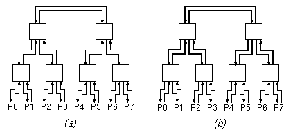
(a) Show a traffic pattern that saturates the 8+8=16 I/O links (the links connected to the ports P0 through P7), yet can be supported by this network; do not use the trivial traffic pattern where all traffic is among odd-even port pairs (neighbors) -- let some portion of the traffic go through the upper levels of the tree.
(b) Show a traffic pattern that canNOT be sustained by this network, although the capacity limits of the I/O links are not violated; in other words, give a traffic pattern that proves that this network exhibits internal blocking.
Figure 1
(c) Now, consider the network of figure 1(b), which is identical to the one of figure 1(a) except that the links shown in thick lines (the upper two levels of links) have a transmission capacity of 2.0, each. Answer question (a) for this network (show that more "non-local" traffic can be supported this time).
(d) Answer question (b) for this latter network of figure 1(b), i.e. show that this network too has internal blocking.
(a) Prove that the network of figure 2(a) has no internal blocking.
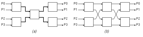
Figure 2
(b) Now, consider the network of figure 2(b), which consists of two banyans connected back-to-back with their middle stages merged. This network can be thought of as resulting from that of figure 2(a), using inverse multiplexing for the double-rate links and switch. Here, all links have a capacity of 1.0, each. Notice that this is a multi-path network: there are more than one paths --actually two paths-- from any given input port to any given output port. Try finding a traffic pattern that cannot be sustained by this network although it is within the capacity limits of the I/O links; you will probably not find any, because this network has no internal blocking, when routing (path selection) in done in an appropriate way.
(c) When all packets of a flow follow a same, single path, show that flows in the dual-banyan network of figure 2(b) may need rerouting in order for the non-blocking property to be satisfied. Consider, for simplicity, flows of rate 1.0 each; in this case, there is a single flow per input port and a single flow per output port (flows among identically numbered ports are allowed). Start setting up flows, one by one, using one of the two possible routings for each new flow (in some cases, the flows that have already been established will dictate a single routing choice for the new flow). Give a sequence of such flow set-up's and routing choices such that when a request for a new flow arrives (between two non-busy ports), this new flow can only be satisfied if some previously established flow(s) are rerouted, i.e. previous routing decisions are revised. We call these rearrangeably non-blocking networks.
(d) The proper definition of inverse multiplexing differs from the routing assumption made in the first sentence of question (c). How would the routing choices of question (c) differ if proper inverse multiplexing is used? Would rerouting (revision of previous routing decisions) ever be needed if proper inverse multiplexing is used?
Consider the situation where a packet destined to a gigabit Ethernet output arrives through an OC-12 input. The maximum-sized Ethernet packet is 1518 bytes long, and, when arriving through an ATM port, it arrives segmented into 32 ATM cells (1518 bytes / 48 payload-bytes/cell = 31.63 cells). The first 1518 bytes in the (48-byte) payloads of the 32 cells are precisely the 1518 bytes that constitute the Ethernet packet. Assume that we are guaranteed that these 32 cells will always arrive back-to-back, without any idle cells in-between them (when ATM traffic is carried over SONET links, cells are always transmitted back-to-back, without any "spacing" between them other than the SONET overhead bytes; however, in general, not all cells need to be valid --idle cells can be freely injected into the SONET payload in the general case, but not in our case between same-packet cells).
How soon, in nanoseconds, after the arrival of the first payload byte of the first ATM cell of the above 32-cell train can we transmit the first byte of the 8-byte gigabit Ethernet preamble? Obviously, right after the 8-byte preamble is transmitted, the 1518 bytes of the Ethernet packet must be transmitted, back-to-back, at the gigabit Ethernet rate, without any "hiccups". Our switch circuits are able to transmit any given byte within 100 ns at the earliest, after that byte is received at an input port.
(a) Today, the processor in this example would run at, say, 667 MHz, instead of 133 MHz. How would the answers in the example change owing to this? Assume for the moment that the interrupt latency stays fixed, and that so does the time to access packet data from memory or I/O (the latter are not sped up much by the faster clock because many of these accesses refer to I/O or miss in the caches). Although the processor has become 5 times faster, the router throughput has increased by a much lower percentage --how much? Why is this so? Which are the dominant delays?
(b) Further to the faster clock in (a), assume that the interrupt latency is now reduced to 2 microseconds. How does this change your answers in (a)? Give each of your two answers both in Mbits/s and Mpackets/s.
(c) Further to (b), assume now that the mean packet size becomes 64 bytes instead of 500 bytes. How does this change your answers in (b)? Do the Mpackets/s increase or decrease? Do the Mbits/s increase or decrease? Why?
(d) Further to (c), assume that we now use this system to switch ATM cells. Ignoring the (very heavy, unfortunately) call set-up overhead, assume that the only changes are: (i) the packet size is 53 bytes, instead of 64 or 500; (ii) the packet forwarding code takes 50 machine cycles, instead of 200; and (iii) the packet header is 4 bytes, instead of 20. What are now the two thrpoughput values, in Mbits/s and Mpackets/s?
(a) What is the PCI throughput, in Mbps, in the following 4 cases?
(b) If a first generation switch without DMA is built around a PCI bus, and the system bottleneck is the PCI bus, what would be maximum switch throughput (= aggregate incoming throughput = aggregate outgoing throughput), in Mbps, in the four cases of part (a)?
(c) Same question as (b), but for a first generation switch with DMA.
(d) Same question as (b), but for a second generation switch.
| Up to the Home Page of CS-534 |
© copyright University of Crete, Greece.
Last updated: 08 Oct. 2001, by M. Katevenis. |