CS428 Embedded Systems Lab
Assignment 4: I2C
This assignment aims to help you understand how the I2C protocol works and how to access other devices with it.
1. Get a kit from the lab
For this assignment, you will need:
· the Arduino DUE board,
· the main shield,
· the display shield,
· the led module,
· the speaker module, and
· the gyroscope module, and
· a USB cable.
Details on the procedure you need to follow to get access to these will be given in class.
2. Download the assignment repo
Refer to the assignments page for information about forking the assignment repo. Fork and clone the repo as4_i2c.
3. Connect the required components to the Arduino DUE board
· This is your Arduino board [pinout, schematic].
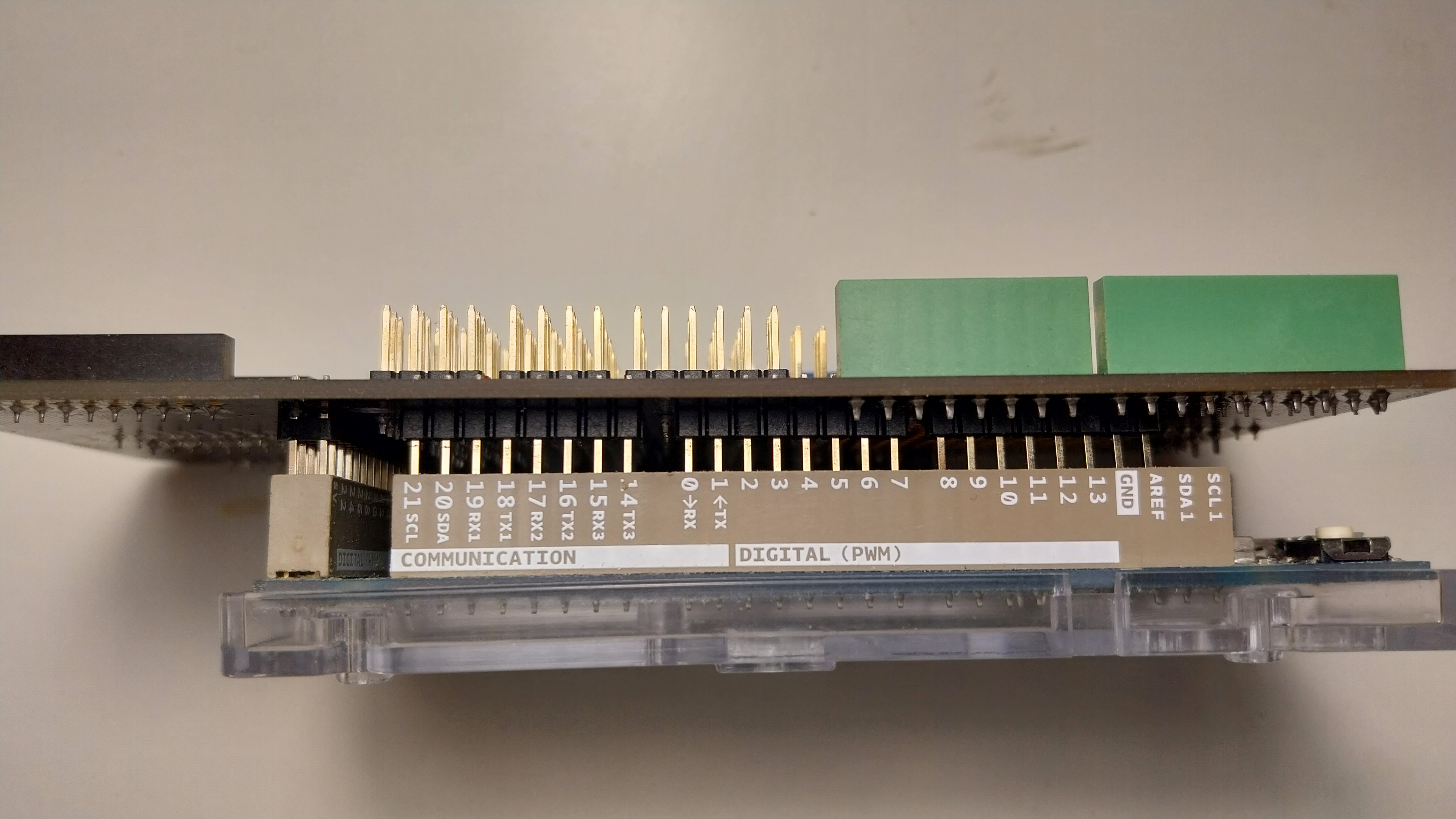
· Add the gpio expansion shield on top. Align the board sides and the pins carefully, as shown here. Be careful not to bend any of the pins. Make sure that all the pins between the shield and the Arduino are connected firmly.
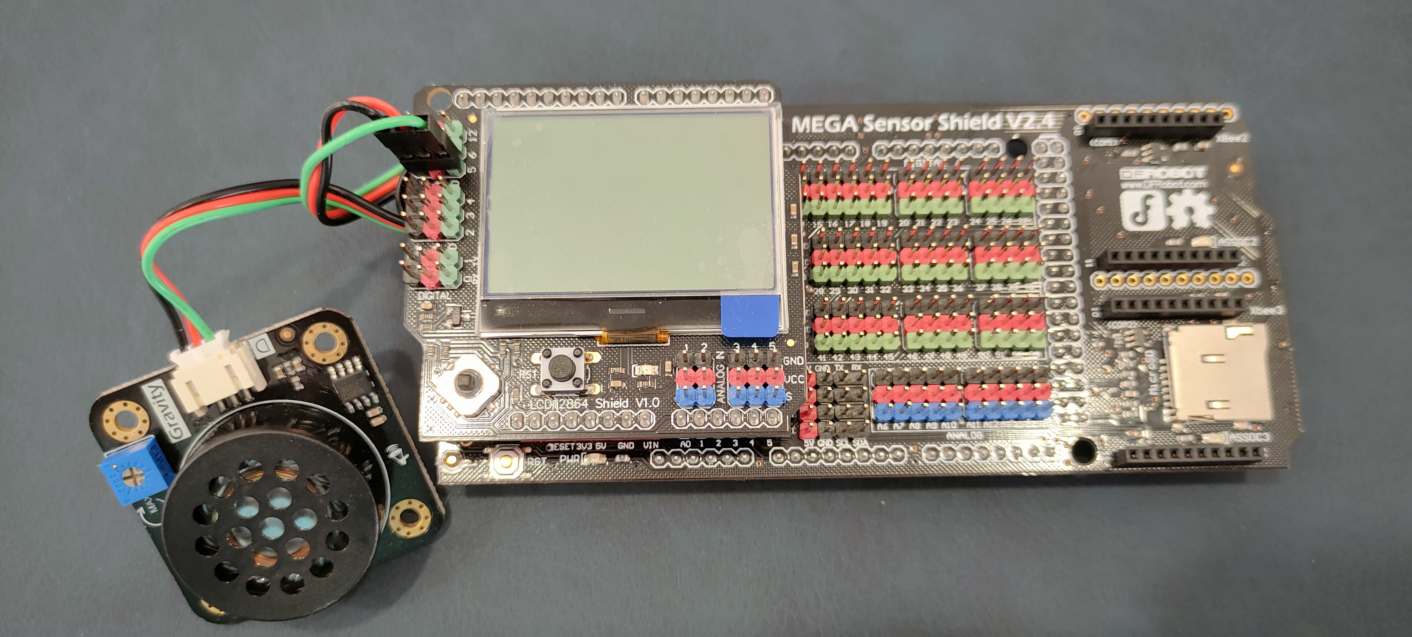
· Add the display shield on top of the gpio shield.
· The green led is a Digital Piranha Green LED v2 module. Connect the LED module to the 2nd pin triplet on the display shield matching wire and pin colors. Connect the positive red wire to the red + pin, the negative black to the black - pin, and the signal green to the green D pin. Take a look at the Arduino due pinout pdf for more details on where each pin goes and what is does.
· This is the speaker module [schematic]. Connect the speaker module to the 5th pin triplet on the display shield matching wire and pin colors. Connect the positive red wire to the red + pin, the negative black to the black - pin, and the signal green to the green D pin. Take a look at the Arduino due pinout pdf for more details on where each pin goes and what is does.
· Our LCD display is an LCD12864 and uses the ST7565 controller/driver to operate the display. ST7565 accepts commands from the ARM core over SPI.
· This is your BMX160 gyroscope module (BMX160 schematic). Alternatively, you can also use a BMI160 gyroscope module (BMI160 schematic). Connect the gyroscope module to the I2C port on the gpio expantion shield. The red positive wire connects to the red pin labeled 5v, the negative black wire connects to the pin labeled GND, the blue wire connects to the pin labeled SCL and the green wire connects to the pin labeled SDA.
4. Build our basic firmware
The as4_i2c directory contains the skeleton of a very simple program/firmware. To build this firmware:
1. Go to the as4_i2c directory.
2. Copy the orig directory to a new directory for your solution to the assignment with “cp -r orig solution”.
3. Go to the solution directory and type “make clean; make”.
3. Go to the solution directory and adjust the Makefile, similar to the first assignment.
4. In the solutions directory, type “make system; make clean; make”.
5. Create an as4_readme.txt file that will contain your answers to questions below.
3. Extend the firmware to setup and use the Inter-Integrated Circuit (I2C)
Read the course slides on how the I2C protocol works. The I2C peripheral in SAM3X8E is referred to as Two Wire Interface (TWI) and is described in Section 33 of atmel_SAM3X8E_datasheet.pdf. For this assignment, we will be using the TWI1 peripheral configured as master. We will use a speed of 100KHz for our implementation.
3.1 To which PIO, pin, and peripheral map the pins SDA and SCK?.
3.2 Implement the following functions of an I2C module with the i2c.h interface:
void i2c_init(void); //a sketch of this function is provided
void i2c_write(uint8_t address, uint8_t *data, uint32_t len); //synchronous write
void i2c_read(uint8_t address, uint8_t *data, uint32_t len); //synchronous read
// in questions 5,6 you will be asked to also implement
void i2c_write_async(uint8_t address, uint8_t *data, uint32_t len); //asynchronous write with interrupts
void i2c_read_async(uint8_t address, uint8_t *data, uint32_t len); //asynchronous read with interrupts
void i2c_write_async_dma(uint8_t address, uint8_t *data, uint32_t len); //asynchronous write with DMA and interrupt completion
void i2c_read_async_dma(uint8_t address, uint8_t *data, uint32_t len); //asynchronous read with DMA and interrupt completion
4. Gyroscope
The device we will be using is the BMX160+BMX388 sensor. BMX160 includes an accelerometer, a gyroscope, and a geomagnetic sensor. BMX388 includes a barometric pressure and temperature. We will setup and use only the gyroscope(Sections 2.1, 2.4.2, 2.11, and in particular 2.11.4 of BMX160) but feel free to experiment with the rest of the sensors as well. The gyroscope measures rotational speed, so you need to rotate it to get any data from it. BMX160 can be accessed via I2C (Section 3 of BMX160). Alternatively, you can use a BMI160 sensor that has identical characteristics.
4.1 What is the device address when using I2C? Note that the boards that have the BMX/BMI variants use different I2C addresses, so use the appropriate address for your sensor. Use the schematics and the datasheet of each sensor board and explain why each sensor has the specific address. Which BMX160/BMI160 DATA registers contain the gyroscope data and in what form?
4.2 Implement the following functions of the gyro.h module:
void gyro_init(void); //initialize the gyroscope over I2C
uint8_t gyro_idread(); //read the id from the device
void gyro_read(void); //read current gyro data from the device and fill in the global variable gyro
void gyro_regwrite(uint8_t addr, uint8_t val); //write a gyro control register on the device
void gyro_regread(uint8_t addr, uint8_t *val, uint32_t len); //read a gyro control register from the device
void gyro_getpos(int16_t *posx, int16_t *posy, int16_t *z); //return the last (x,y,z) state that was read from the device
4.5 Modify your firmware to display the gyroscope position as you move it around.
5. I2C with Interrupts.
The previous I2CWrite/I2CRead were blocking functions, meaning that the processor must wait for the slow I2C bus to finish transmitting the entire buffer in order to continue executing the code. This implementation results in millions of CPU cycles lost while waiting for the bus to finish. By using interrupts, we can send the first byte ourselves and then rely on interrupts to know when to send another byte, making this process mostly asynchronous.
You are given the following interface for the I2C functions using interrupts:
void i2c_write_async(uint8_t address, uint8_t *data, uint32_t len); //asynchronous write with interrupts
void i2c_read_async(uint8_t address, uint8_t *data, uint32_t len); //asynchronous read with interrupts
5.1 Implement the two functions above. i2c_write_async() enables interrupts and sends the first byte to the bus. After that, the interrupt handler sends the remaining data. You will need a way to keep track of the state of the peripheral during the interrupts. i2c_read_async() works in a similar way. Make sure that before you enable any interrupts to acknowledge/assert any registers that can raise an interrupt. You can do this by performing a dummy read on SAID register.
5.2 Test your functions by replacing i2c_write() and i2c_read() in the gyroscope library with your new ones
6. I2C with DMA(Direct Memory Access).
We can make both writes and reads on the I2C bus (almost) asynchronous using the DMA functionality. Read the atmel_SAM3X8E_datasheet.pdf to learn how the DMA peripheral works. In the atmel_SAM3X8E_datasheet.pdf, the DMA peripheral is referred to as PDC (Peripheral DMA Controller).
You are given the following interface for the I2C functions using DMA:
void i2c_write_async_dma(uint8_t address, uint8_t *data, uint32_t len); //asynchronous write with DMA and interrupt completion
void i2c_read_async_dma(uint8_t address, uint8_t *data, uint32_t len); //asynchronous read with DMA and interrupt completion
6.1 Implement i2c_write_async_dma() & i2c_read_async_dma(). If you take a look at the flowcharts for reading operations, you will notice that the stop condition must be sent before the last byte is read. When the DMA peripheral handles our data, we do not know the state of our transaction. For this reason, i2c_read_async_dma() will read all but the last 2 bytes of data using DMA, and the rest will be read manually through interrupts in order to send the Stop condition.
6.2 Test your functions by replacing i2c_write_async_dma() & i2c_read_async_dma() in the gyroscope library with your new ones
7. Display the gyroscope data
7.1 Write a simple program to read and display the gyroscope data in a coordinate system with two axes using a moving dot on the display and/or coordinate numbers.
8. Submit
Please refer to the policies for information about the submission process.
8.1 Submit all files required to run the assignment, including your documentation file as4_readme.txt with all your answers and remarks.
8.2 Follow the procedure outlined in class for returning the components you used in this assignment.
(c) Copyright University of Crete, Greece, Last Modified: 03-April-2024.