CS428 Embedded Systems Lab
Assignment 3: Display
This assignment aims to help you understand:
(a) How the display works and how to provide a simple driver and
(b) How analog to digital converters work and how to provide a simple driver.
1. Get a kit from the lab
For this assignment, you will need:
· the Arduino DUE board,
· the main shield,
· the display shield,
· the led module,
· the speaker module, and
· a USB cable.
Details on the procedure you need to follow to get access to these will be given in class.
2. Download the assignment repo
Refer to the assignments page for information about forking the assignment repo. Fork and clone the repo as3_display.
3. Connect the required components to the Arduino DUE board
· This is your Arduino board [pinout, schematic].
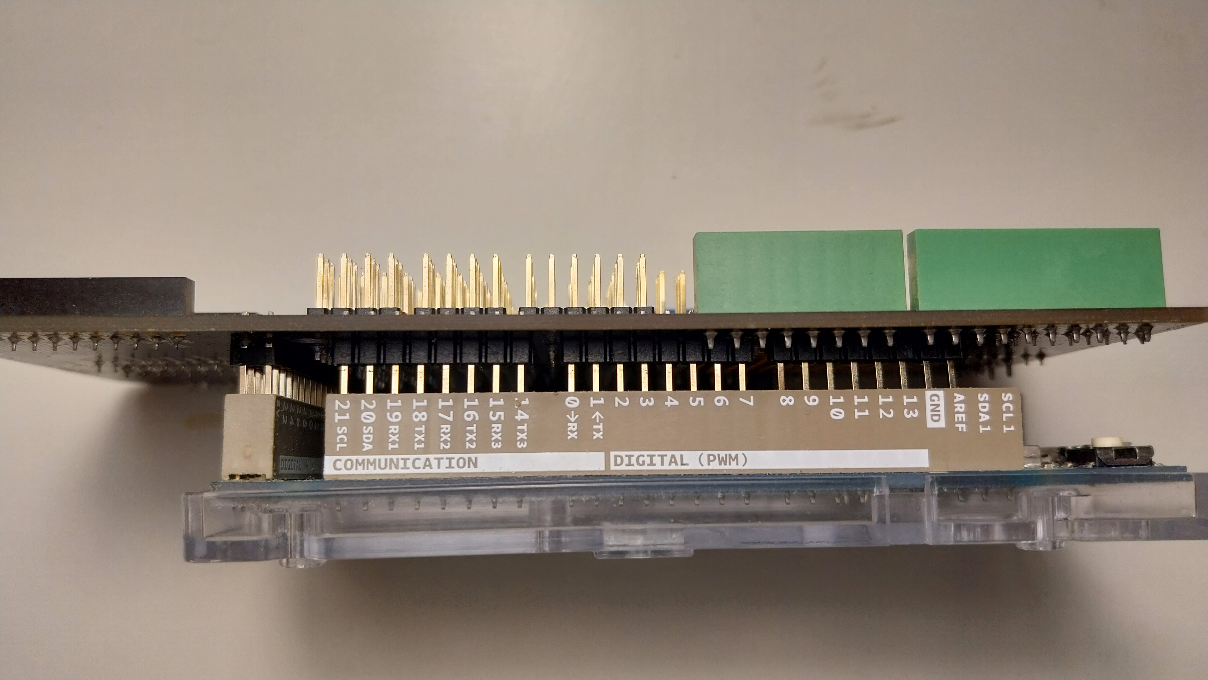
· Add the gpio expansion shield on top. Align the board sides and the pins carefully, as shown here. Be careful not to bend any of the pins. Make sure that all the pins between the shield and the Arduino are connected firmly.
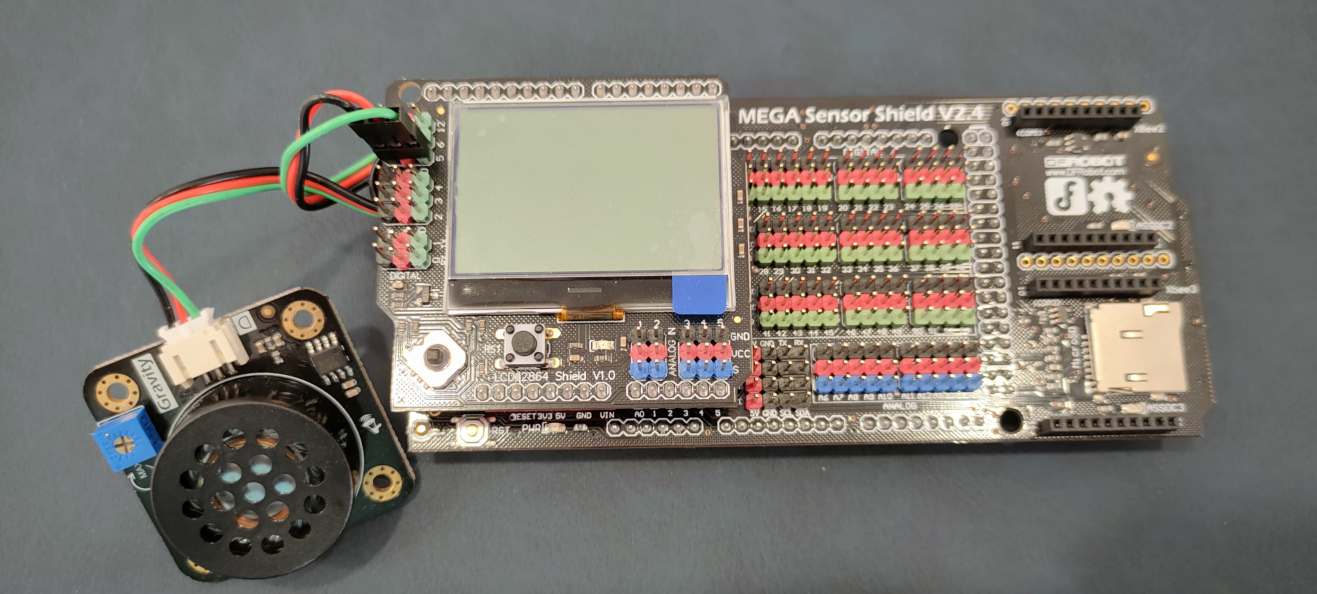
· Add the display shield on top of the gpio shield.
· The green led is a Digital Piranha Green LED v2 module. Connect the LED module to the 2nd pin triplet on the display shield matching wire and pin colors. Connect the positive red wire to the red + pin, the negative black to the black - pin, and the signal green to the green D pin. Take a look at the Arduino due pinout pdf for more details on where each pin goes and what is does.
· This is the speaker module [schematic]. Connect the speaker module to the 5th pin triplet on the display shield matching wire and pin colors. Connect the positive red wire to the red + pin, the negative black to the black - pin, and the signal green to the green D pin. Take a look at the Arduino due pinout pdf for more details on where each pin goes and what is does.
· Our LCD display is an LCD12864 and uses the ST7565 controller/driver to operate the display. ST7565 accepts commands from the ARM core over SPI.
4. Build our basic firmware
The as3_display directory contains the skeleton of a very simple program/firmware. To build this firmware:
1. Go to the as3_display directory.
2. Copy the orig directory to a new directory for your solution to the assignment with “cp -r orig solution”.
3. Go to the solution directory and adjust the Makefile, similar to the first assignment.
4. In the solutions directory, type “make system; make clean; make”.
5. Create an as3_readme.txt file that will contain your answers to questions below.
5. Extend the firmware to setup and use the Serial Peripheral Interface (SPI)
Our display uses the SPI protocol for communication with the processor core. However, our display shield does not (cannot) connect to the SPI peripheral of SAM3X8E (atmel_SAM3X8E_datasheet.pdf). Instead, it connects to other pins of PIO controllers and we will use these pins to emulate SPI and send commands to the display. Our display connects to the following Arduino DUE pins:
Pin Use for PIO-pin#
Digital 13(D13) SPI SCK PB27
Digital 11(D11) SPI MOSI PD7
Digital 10(DO) SPI CS PA28
Digital 9(D9) SPI CD PC21
Digital 8(D8) SPI RST PC22
Digital 7(D7) LCD backlight control PC23
Analog0(A0) 5-degree joystick control PA16
5.1 To which PIO controller does our display connect? Which PIO pin correspond to each display pin? Fill in this information in the table above.
5.2 At what SPI speeds can the display operate? What is the required clock cycle for the SPI transfers (half in the low clock pulse and half in the high clock pulse)?
5.2 Implement the following functions that allow us to send (write) information to the display over the (emulated) SPI protocol in spi.h:
void spi_init(void); // init PIO pins
void spi_setcs(uint32_t cs); // enable/disable display
void spi_writebit(uint8_t byte); // if byte is 0 then bit is 0, otherwise bit=1.
// set the clock low, high properly so that SPI speed matches display capabilities
void spi_writebyte(uint8_t data); // write a byte, MSB first
void spi_write(uint8_t *buf, uint32_t len); // write a buf array of len bytes
6. Extend the firmware to setup and use the display
Our display is an LCD12864 and uses the ST7565 controller/driver to operate the display. ST7565 accepts commands from the ARM core over SPI. Table 16 on page 41 of the ST7565 datasheet summarizes the commands available in the ST7565.
To update the LCD we will use a simple technique that works for both characters and graphics: We will use a program frame buffer that will hold the state of each LCD pixel, we will be updating pixels only in the frame buffer, and from time to time we will be sending the full frame buffer to the LCD (via the SPI). The frame buffer can be a 2D array uint8_t FrameBuffer[#pages][#columns]. To display a character we need to update a set of bytes in this array. To display (or clear) a pixel, we need to modify a single bit in some array position/byte. The font for characters is provided in font.[ch]. Each character is a 6x8 array of pixels which is represented as a sequence of 6 bytes in the font array.
6.1 Define your frame buffer and write a function that sends the full frame buffer to the display via the SPI:
void display_init(void); //initialize the diplay; A sketch of this function is provided
void display_update(void); // send the full frame buffer to the display
Note, that these are the only two functions that manipulate the display (LCD) itself.
6.2 Using only the frame buffer, implement the following functions of display.h for performing basic functions with our display:
void display_clear(); //set all pixels to 0 in the frame buffer
void display_char(uint8_t i, uint8_t j, char c); //write a char at page i, column j in the frame buffer
void display_str(uint8_t i, uint8_t j, char *str); //write a string at page i, column j in the frame buffer
void display_num(uint8_t i, uint8_t j, uint32_t num, uint8_t width); //write num as width digits at page i, column j in the frame buffer
void display_setpixel(uint8_t i, uint8_t j, uint8_t value); // set pixel i,j to value=0,1 in the frame buffer
7. Setup and use the Analog-to-Digital Converter (ADC)
The analog-to-digital converter (ADC) (Section 43 in atmel_SAM3X8E_datasheet.pdf) takes an analog voltage from one of the pins of the Arduino and converts it to a digital value. The display module contains a 5-position joystick button. This button outputs a different voltage depending on its position (display board/shield schematic).
7.1 To which PIO and pin is the 5-position joystick connected? Which peripheral (A or B) for this PIO pin is the ADC? Based on this pin, which ADC channel does the joystick use? In this case, no initialization is required for the PIO peripheral, as the ADC itself handles this. The ADC itself needs to be configured with no hardware triggers, 64 periods startup time, 17 periods settling time, tracking time 3, transfer period 2, single-ended mode, and gain of 1.
7.2 Implement the following functions that allow us to convert analog signals to numerical values via the ADC, in adc.h:
void adc_init(void); //setup ADC. A sketch of this function is provide.
void adc_enable(uint32_t channel); //start conversion on ADC channel
void adc_disable(uint32_t channel); //stop conversion on ADC channel
void adc_start(void); //trigger next coversion
uint32_t adc_status(uint32_t channel); //check if next value is available
uint32_t adc_read(uint32_t channel); //read next sample, synchronously
7.3 What sampling rate should you use for the joystick? Use the appropriate value for the PRESCALE parameter in ADC_MR.
7.4 Modify your firmware to read and display the state of the joystick.
8. Implement an Analog Clock
You will now draw simple graphics on the screen to display an analog clock. You will need to use simple math functions form math.h and to include the math library -lm in your Makefile and in the proper order with the rest of the libraries).
8.1 Implement the following functions in the aclock.h module:
//draw the frame at cx,cy with radius r
void aclock_frame(uint8_t cx, uint8_t cy, uint8_t r);
//draw a hand with origin cx,cy, length r, and tick t in [0,59]
void aclock_hand(uint8_t cx, uint8_t cy, uint8_t r, uint16_t t);
//draw a symbol, e.g. a fat dot, on the frame (x,y,r) at angle a
void aclock_framesymbol(uint8_t cx, uint8_t cy, uint8_t r, uint16_t d);
//draw the full thing at x,r with radius r for hh:mm:ss
void aclock_display(uint8_t x, uint8_t y, uint8_t r, uint8_t hh, uint8_t mm, uint8_t ss);
8.2 Modify your firmware to display an analog clock on the display and update the hand motion every second.
9. Submit
Please refer to the policies for information about the submission process.
9.1 Submit all files required to run the assignment, including your documentation file as3_readme.txt with all your answers and remarks.
9.2 Follow the procedure outlined in class for returning the components you used in this assignment.
(c) Copyright University of Crete, Greece, Last Modified: 18-July-2023.