CS428 Embedded Systems Lab
Assignment 2: Timers, interrupts, & sound
The goal of this assignment is to help you understand timers, interrupts, and introduce you to generating sounds via the corresponding communication protocols/peripherals.
1. Get a kit from the lab
For this assignment, you will need:
· the Arduino DUE board,
· the main shield,
· the display shield,
· the led module,
· the speaker module, and
· a USB cable.
Details on the procedure you need to follow to get access to these will be given in class.
2. Download the assignment repo
Refer to the assignments page for information about forking the assignment repo. Fork and clone the repo as2_dclock.
3. Connect the required components to the Arduino DUE board
· This is your Arduino board [pinout, schematic].
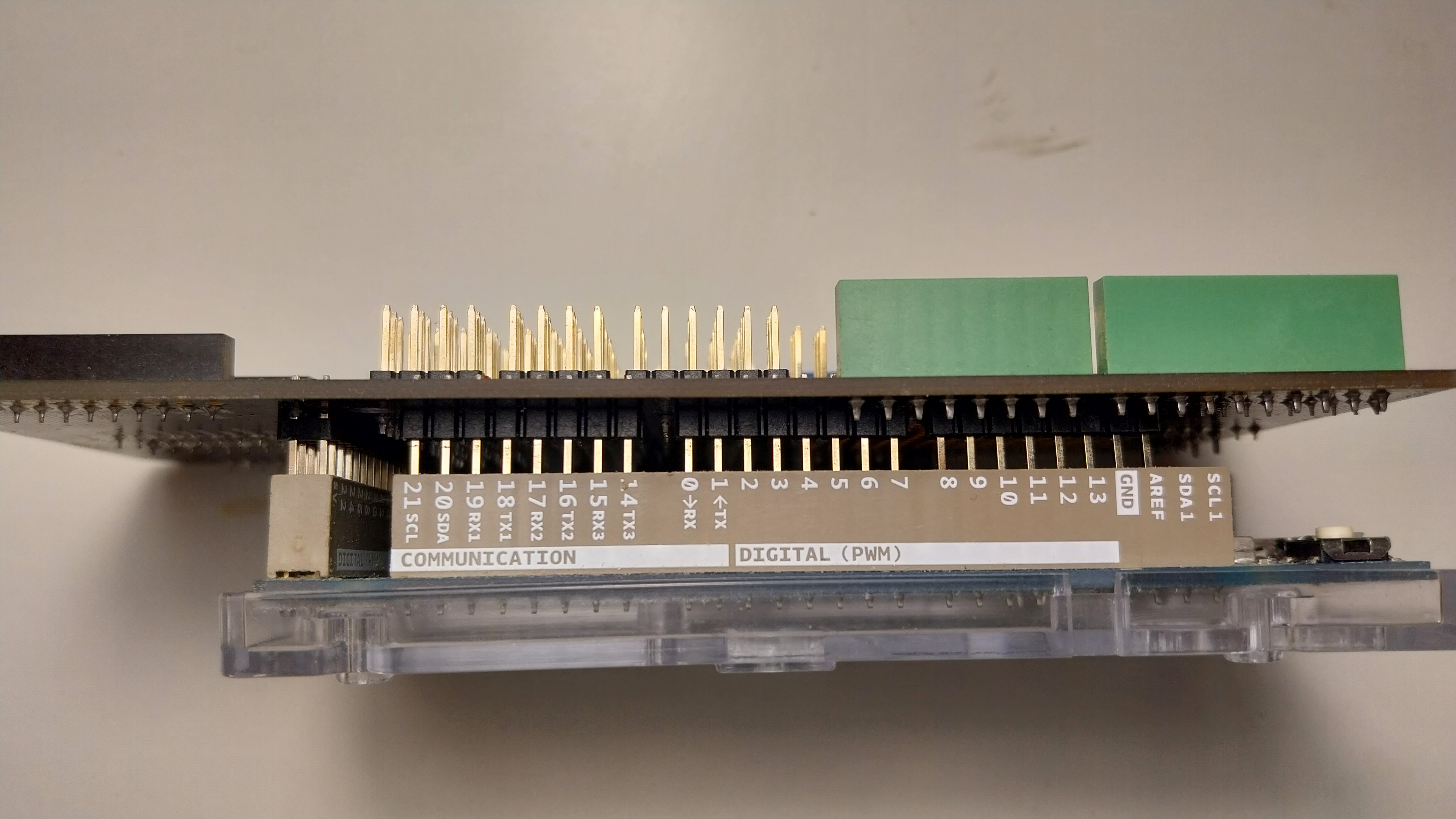
· Add the gpio expansion shield on top. Align the board sides and the pins carefully, as shown here. Be careful not to bend any of the pins. Make sure that all the pins between the shield and the Arduino are connected firmly.
· Add the display shield on top of the gpio shield.
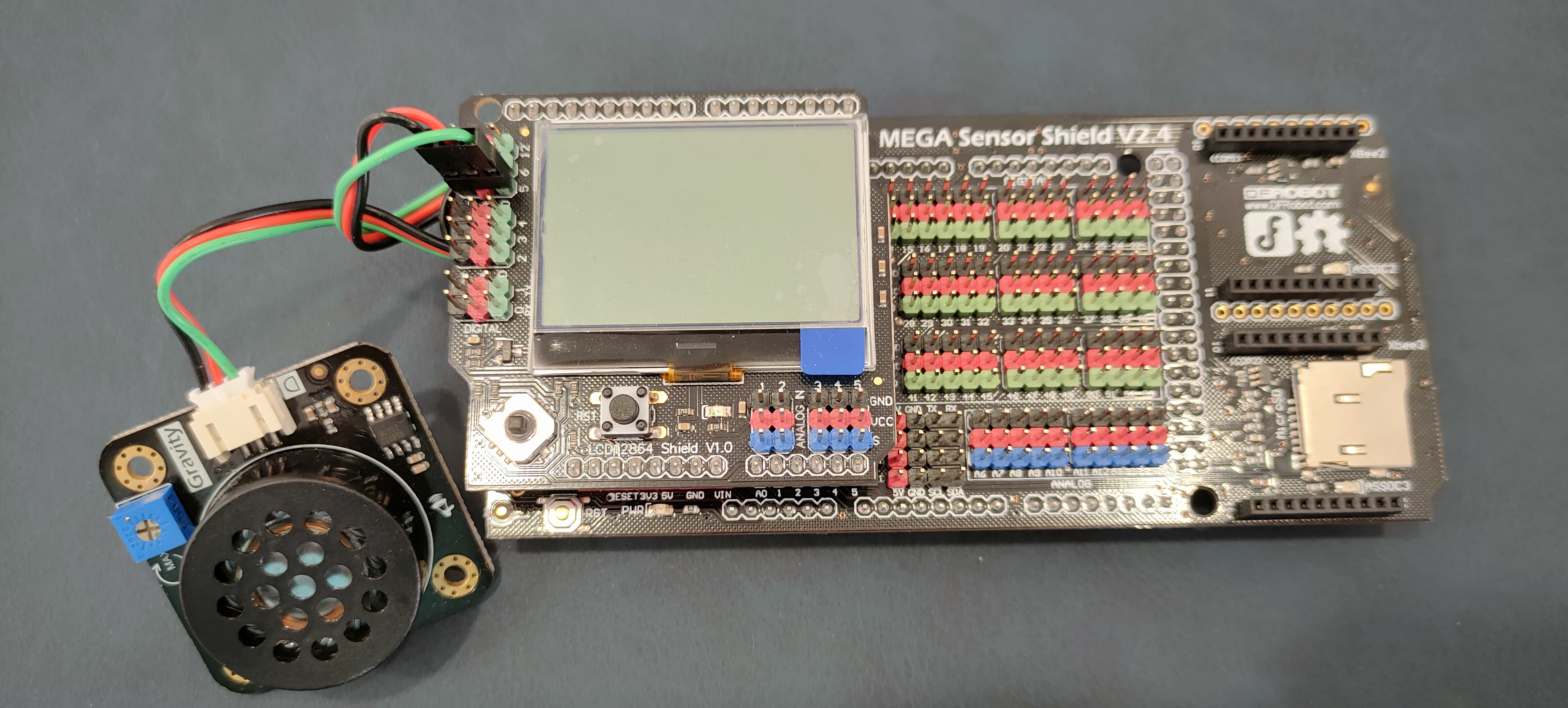
· The green led is a Digital Piranha Green LED v2 module. Connect the LED module to the 2nd pin triplet on the display shield matching wire and pin colors. Connect the positive red wire to the red + pin, the negative black to the black - pin, and the signal green to the green D pin. Take a look at the Arduino due pinout pdf for more details on where each pin goes and what is does.
· This is the speaker module [schematic]. Connect the speaker module to the 5th pin triplet on the display shield matching wire and pin colors. Connect the positive red wire to the red + pin, the negative black to the black - pin, and the signal green to the green D pin. Take a look at the Arduino due pinout pdf for more details on where each pin goes and what is does.
4. Build a very simple first firmware
The as2_dclock directory contains the skeleton of a very simple program/firmware. To build this firmware:
1. Go to the as2_dclock directory.
2. Copy the orig directory to a new directory for your solution to the assignment with “cp -r orig solution”.
3. Go to the solution directory and adjust the Makefile, similar to the first assignment.
4. In the solutions directory, type “make system; make clean; make”.
5. Create an as2_readme.txt file that will contain your answers to questions below.
5. Display the time as HH:MM:SS
5.1 Add to the assignment firmware (dclock.h, dclock.c) a function that displays time in the format HH:MM:SS (you can always make it more fancy if you want):
void dclock_display(uint8_t X, uint8_t Y, uint8_t hh, uint8_t mm, uint8_t ss);
6. Setup and use the timer counter (TC)
Read Section 36 of the atmel_SAM3X8E_datasheet.pdf on the Timer Counters (TC) (you can devote less time to the sections about waveform mode/selection and the quadrature decoder 36.6.10-14).
6.1 Which files in the “system” directory contain definitions and which ones contain code that is executed? List the files that contain code.
6.2 The MCK value refers to the ARM Cortex-M3 processor clock speed in SAM3X8E. What is the MCK value for your kit?
6.3 How many timer counters does our system have? Which file(s) in the “system” subdirectory of the assignment contain the #define definitions for the addresses and other parameters of TC? To which timer counter and in which channel does TC5 correspond to? How do you address in code the current value of (timer counter 0, channel 1);
6.4 Implement the following functions of a module for any (timer counter, channel) in a tc.h interface:
void tc_init(Tc *tc, uint8_t channel, uint32_t rc); // tc is TC0,TC1,TC2; channel is 0,1,2; usa CLOCK1=MCK/2=42MHz;
// disable all interrupts; set RC to rc
void tc_enable(Tc *tc, uint8_t channel); // reset and start counting on timer counter tc (TC0,TC1,TC2), channel c (0,1,2)
void tc_disable(Tc *tc, uint8_t channel); // stop counting on timer counter tc (TC0,TC1,TC2), channel c (0,1,2)
void tc_spinus(Tc *tc, uint8_t channel, uint32_t us); // spin for us usecs
6.5 What is the largest delay you can achieve with a timer counter?
6.6 Update your main function to use TC1 (timer counter 0, channel 1) via the module tc.h for introducing exact delays when counting time.
7. Setup and use the Nested Vectored Interrupt Controller (NVIC)
Read Section 10.20 of the atmel_SAM3X8E_datasheet.pdf on the Nested Vectored Interrupt Controller (NVIC). Which file in the system directory contains the definitions for NVIC; Via which array variable declaration are the 32-bit priority registers of NVIC (IPR in the manual) viewed; What is the size (bits) of each element and how many elements correspond to each 32-bit register? Which bits within each element are related to the interrupt priority; How do you need to index this array to set the priority p for an interrupt irq;
7.1 The file system/sam3x8e.h defines all interrupt numbers as an enum type IRQn_Type. How many interrupts (excluding processor exceptions) does NVIC handle? What values can priorities have? Which one is higher?
7.2 Implement the functions of a module for NVIC which provides the following interrupt.h interface:
void nvic_enable(IRQn_Type irq); // enable interrupt irq
void nvic_disable(IRQn_Type irq); // disable interrupt irq
void nvic_setpriority (IRQn_Type irq, uint32_t prio); // set priority of irq to priority
8. Setup and use TC interrupts
8.1 Implement the following additional functions in the tc.h interface:
void tc_int_enable(Tc *tc, uint8_t ch, uint32_t t); // enable interrupts every t usecs using RC comparison for timer counter tc (TC0,TC1,TC2), channel c (0,1,2)
void tc_int_disable(Tc *tc, uint8_t ch, uint32_t rc); // disable interrupts and reset RC to rc (to avoid frequent wrap-around) for timer counter tc (TC0,TC1,TC2), channel c (0,1,2)
void tc_int_ack(Tc *tc, uint8_t channel); // ack an interrupt by reading the status register for timer counter tc (TC0,TC1,TC2), channel c (0,1,2)
8.2 Which interrupt handler is used by TC1? Where is this handler defined and how is it placed in memory? When is this handler invoked during execution? How is the handler invoked?
8.3 How can you provide your own handler for the timer? What does it mean for a handler to acknowledge a device interrupt reading the device SR? Do you need to do this?
8.4 Configure TC1 to generate an interrupt every 10 seconds. Provide the interrupt handler to update and display the time every 10 seconds, without spinning.
9. Make the clock generate a sound every 10 seconds
Read Section 36 of the atmel_SAM3X8E_datasheet.pdf on how the Timer Counter peripheral can produce PWM (Pulse Width Modulation) waveforms. There are several ways to generate PWM signals. We will use the PIOA output of TC6 (timer counter 2, channel 0) as this is mapped to D5 of the display shield, where we connected the speaker module.
9.1 Implement the following additional functions in the tc.h interface:
void tc_pwm_init(Tc *tc, uint8_t c, uint32_t T, uint8_t D); // same as tc_init() but setup RC, RA timer to generate PWM with parameters T,D on output PIOAx
9.2 Output TIOA6 drives pin D5. To figure out this path, answer the following questions:
· To which PIO controller does TIOA6 connect?
· Which pin on this PIO controller does it connect to?
· Which peripheral (A or B) on this pin does it correspond to?
9.3 We need to enable/setup this PIO controller and the corresponding pin as output and select the appropriate peripheral so that TIOA6 is passed through to the sound amplifier and speaker. To do this, perform the following actions in a function in the sound.h interface:
void sound_init (void){
//enable the appropriate PIO on PMC using PMC_PCER
//allow PIO registers to be written using PIO_WPMR
//configure the appropriate pin to be controlled by a peripheral (not PIO) using PIO_PDR
//enable pin as output using PIO_OER
//select the right peripheral (A or B) by using PIO_ABSR
}
9.4 Implement the functions of a module for generating sounds which provides the following sound.h interface:
void sound_init(void); // as above
void sound_start(uint16_t f, uint8_t v); // start generating a sound with freq f in [20,20000] Hz and volume v in [0,100]
void sound_stop(void); // stop generating a sound
void sound(uint16_t f, uint8_t v, uint32_t ms); // generate a sound of frequency f, volume v, for ms miliseconds; return after the sound has ended
9.5 Modify your firmware so that your digital clock generates a half-a-second sound of increasing frequency from 20 Hz to 20000 Hz every 10 seconds.
10. Extra credit
10.1 Measure the accuracy of your digital clock over a longer period. How accurate is it?
10.2 Is it possible that interrupts are lost while your program is running? How can this happen and what does it mean for each peripheral you use?
10.3 Is it possible to receive nested interrupts? Explain.
10.4 How does the sound get generated after we send our PWM waveform/pattern?
10.5 Can you
control the volume of the sound? Modify your code to use a different sound
volume on the minute.
10.6 Can you generate specific tones? Modify
your code to use a different tones for the 10s beeps.
11. Submit
Please refer to the policies for information about the submission process.
11.1 Submit all files required to run the assignment, including your documentation file as2_readme.txt with all your answers and remarks.
11.2 Follow the procedure outlined in class for returning the components you used in this assignment.
(c) Copyright University of Crete, Greece, Last Modified: 18-July-2023.