CS428 Embedded Systems Lab
Assignment 1: Hello world!
The goal of this assignment is to help you become familiar with the Arduino DUE platform and the tools we will use in the assignments.
1. Get a kit from the lab
For this assignment, you will need:
· the Arduino DUE board,
· the main shield,
· the display shield,
· the led module, and
· a USB cable.
Details on the procedure you need to follow to get access to these will be given in class.
2. Download the assignment repo
Refer to the assignments page for information about forking the assignment repo. Fork and clone the repos system and as1_helloworld.
2.1 Create a file as1_readme.txt that will contain answers to any questions below and your remarks about your implementation.
3. Read about the Arduino DUE board
Read about the main microcontroller (which includes the ARM processor) in the board in atmel_SAM3X8E_datasheet.pdf, the pinout of the board arduino_due_pinout.pdf, and the schematic of the board arduino_due_v02g_schematic.pdf.
Answer the following questions:
3.1 What architecture (ISA) is the processor using and at what clock frequency is our DUE running?
3.2 What type(s) of memory does the processor have access to?
3. Install the bare metal unix toolchain for the Atmega SAM3X8E
For this (and most subsequent) assignments, you will need a system running Linux (Windows will work as well but may require tweaking at places). Many flavors (and kernel versions) of Linux will work, but the assignments (the toolchain) have been tested with Ubuntu. You may use the systems already set up for these purposes in the course lab (Room B.107).
1. Download the course toolchain directory/repository. This includes (for linux and windows) binary files for:
a) The arm-gcc compiler, assembler, and linker utilities (10.3) for AArch32 with bare-metal target (arm-none-eabi) from: https://developer.arm.com/tools-and-software/open-source-software/developer-tools/gnu-toolchain/downloads
b) The bossac utility (1.7.0) to flash (reprogram) the Arduino ARM processor, from: https://github.com/shumatech/BOSSA/releases
(alternatively you can also download the source of the toolchain from the original web pages and build from scratch a local copy for your version of the OS)
2. Extract/install all the ARM tool binary files in a directory $dira. Set the ARMBIN variable at the beginning of the orig/Makefile in assignment 1 to $dira/bin (which contains the executables, e.g. gcc-arm).
3. Extract/install the bossac executable in a directory $dirb. Set the BOSSAC variable at the beginning of the orig/Makefile in assignment 1 to point to the executable itself $dirb/bossac.
4. Set the SYSTEM_REPO variable at the beginning of the orig/Makefile to the path of the system repo you downloaded.
4. Connect the required components to the Arduino DUE board
Use the pinout manual as a reference for the board pin purpose, names, and numbers.
· This is your Arduino board [pinout, schematic].
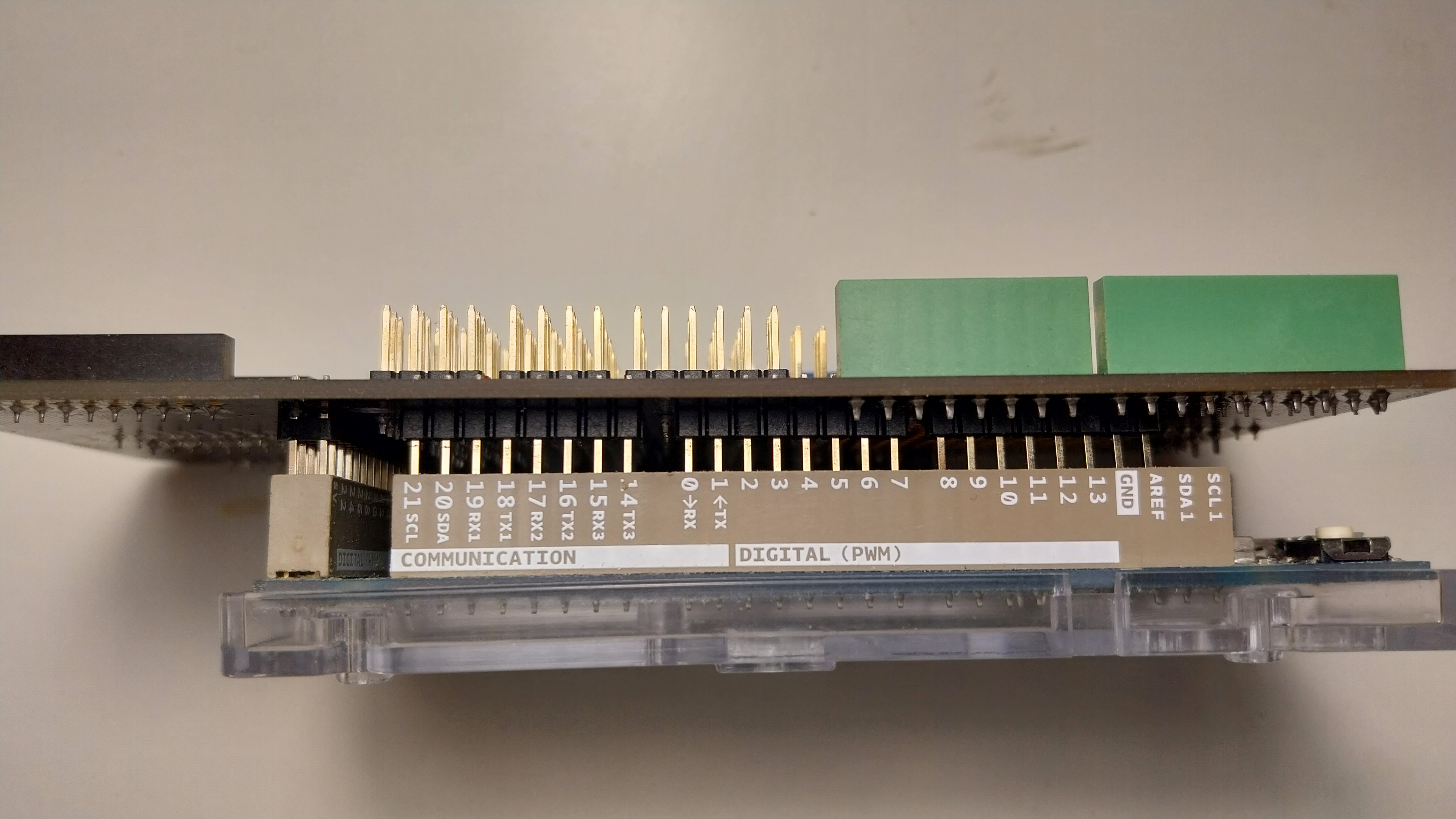
· Add the gpio expansion shield on top. Align the board sides and the pins carefully, as shown here. Be careful not to bend any of the pins. Make sure that all the pins between the shield and the Arduino are connected firmly.
· Add the display shield on top of the gpio shield.
· The green led is a Digital Piranha Green LED v2 module. Connect the LED module to the 2nd pin triplet on the display shield matching wire and pin colors. Connect the positive red wire to the red + pin, the negative black to the black - pin, and the signal green to the green D pin. Take a look at the Arduino due pinout pdf for more details on where each pin goes and what is does.
5. Build a very simple first firmware
The as1_helloworld directory contains the skeleton of a very simple program/firmware. To build this firmware:
1. Go to the as1_helloworld directory.
2. Copy the orig directory to a new directory for your solution to the assignment with “cp -r orig solution”.
3. Go to the solution directory and adjust the Makefile, similar to the first assignment.
4. In the solutions directory, type “make system; make clean; make bin”.
Answer the following questions in the readme file
5.1 Which file contains the main function?
5.2 Which directory(ies) contains the .h files required to build the firmware?
5.3 Does the compilation process use any libraries? Where are these libraries located?
5.4 Add a “pedantic” flag to the CFLAGS in the Makefile. You will notice a number of warnings related to handler function initialization. Fix them by adding a proper type definition for handlers in the file system/sam3x8e.h before the “typedef struct _DeviceVectors” definition, modify the _DeviceVector struct fields to use the new type, and remove the “void *” handler casting in the “const DeviceVectors exception_table” in system/startup.c or replace it with the proper type.
6. Download (flash) the new firmware to the Arduino board
1. Connect your Arduino to your PC. Use the usb port which is next to the black power supply connector.
2. A new entry "ttyACMX" should appear in /dev. Usually this will be ttyACM0, but other numbers (ttyACM1, ttyACM2...) are possible as well. This is the port where your Arduino is located.
3. To ensure that the port can be accessed by a regular user (not superuser) make the following change in file 50-myusb.rules, as follows:
· Go to the directory that contains the file 50-myusb.rules. This should be located in the directory /etc/dev/rules.d/ or /usr/lib/udev/ but could also be in a different directory in the distribution of your OS:
> cd /etc/dev/rules.d/
· If the file does not exist, create an empty 50-myusb.rules file:
> sudo touch /etc/udev/rules.d/50-myusb.rules
· Edit the file with sudo privilege (the directory is protected for regular user write access)
> sudo vi /etc/udev/rules.d/50-myusb.rules
· Add the line:
KERNEL=="ttyACM0",MODE="0666" (replace ttyACM0 with your port)
4. Unplug and replug your Arduino for the previous changes to take effect.
5. Go to your assignment Makefile and set "PROGRAMMING_PORT" at the beginning to your port name for the Arduino board, e.g.:
PROGRAMMING_PORT = ttyACM0
Depending on the OS distribution you use, the “-f” parameter of the “stty -f /dev/$(PROGRAMMING_PORT) 1200” command in the “download” target may need to be capitalized as “-F”. Please consult the man page of stty for the correct parameter (to use the named file instead of the standard input).
6. Type "make download"
(For Windows users: Connect your Arduino to your PC. In Device Manager, select “Ports”. There should be an entry called "Arduino Due Programming Port (COMX)". X can be any number. This is the port where your Arduino is located. Go to your assignment Makefile and add your port to the "PROGRAMMING_PORT" variable, e.g. PROGRAMMING_PORT = COM13. Type "make download_win")
7. Modify the firmware
1. Modify your firmware to display "Hello World!" and blink at about 2 second intervals. Write a function that spins for about 1μs and then use this function. The assignment files include an interface display.h that provides a couple of simple display functions you can use and the interface implementation in display.s. In subsequent assignments we will work on a proper implementation of this interface.
2. Move your delay function in a separate delay.c file and modify the Makefile accordingly.
3. Switch the led of the light module on before and off after the "Hello World!" message is displayed, using the provided led.h module. Similarly to the display, the assignment files include a simple led.h interface and a led.o implementation.
4. Provide an implementation led.c for the led functions. First, you will need to find out to which pin of the Atmel_SAM3X8E you connected the led module. You used pin D2 of the display module. Pin D2 of the display module connects to pin D2 of the Mega Shield. Pin D2 of the Mega Shield connects to pin D2 of the Arduino Due board. Use the pinout diagram of the Arduino Due board to identify to which pin of the Atmel_SAM3X8E is pin D2 connected. Which pin is this?
5. Once you know the pin of Atmel_SAM3X8E, you need to see how you can drive this pin. Use the Atmel_SAM3X8E manual to see which peripheral can drive this pin.
6. Now we need to program this peripheral and drive the led pin properly. We can set the pin to turn the led on and we can clear the pin turn the led off.
7. The led_init() function is given (it mainly sets up the appropriate PIO peripheral, which we will discuss further later on):
void led_init(){
PMC->PMC_PCER0 |= (1U<<ID_PIOB); //enable PIO B on PMC
PIOB->PIO_PER = PIO_PB25; //configure pin for PIO control (not peripheral)
PIOB->PIO_OER = PIO_PB25; //enable pin as output
led_off();
}
8. You will need to implement the led_on() and led_off() functions by using the PIO_SODR/PIO_CODR registers. Which registers of the PIO peripherals can set/clear the output pins? Implement the two functions to set/clear the led pin.
9. Add your led.c implementation of the led.h interface to the Makefile and try it out.
Answer the following questions
7.1 What happens when main returns?
7.2 In your delay function, you use some counting variable. What happens if you declare this to be volatile? Explain briefly.
8. Submit
Please refer to the policies for information about the submission process.
8.1 Submit all files required to run the assignment, including your documentation file as1_readme.txt with all your answers and remarks.
8.2 Follow the procedure outlined in class for returning the components you used in this assignment.
(c) Copyright University of Crete, Greece, Last Modified: 26-May-2023