| CS-534: Packet Switch Architecture
Spring 2007 |
Department of Computer Science
© copyright: University of Crete, Greece |
0. Central Issues in Packet Switching: an Overview
|
[Up: Table of Contents] [Slides 0. Introduction] |
[printer version, in PDF] [Next: 1.1 Throughput and Buffering] |
This section presents an overview
of the central issues and problems
faced in high-performance networking,
and the main alternatives for solving them.
In each particular application domain,
the parameters of the problem have different values,
so different alternatives may be chosen to solve a given problem,
leading to different architectures.
Yet, because all problems have a few, common sources,
these different architectures have several common features,
which we will try to identify in this course.
High-performance networking strives to achieve the highest possible throughput, the lowest possible latency, high utilization of the expensive resources, fair allocation of resources to competing users (QoS guarantees), or combinations of these. When performance is pushed to such extreme points, some pieces of equipment are stressed to operate at rates in excess of what conventional processors can achieve, thus requiring the support of dedicated, special-purpose hardware or processors. This course deals especially with the architecture of these latter parts of the networking equipment.
0.1 Distributed, Multi-Party Communication
Networking deals with multi-party communication; the figure on the right illustrates n systems, S0,... Sn-1, communicating among themselves. Network sizes --the number of communicating parties, n-- vary widely among applications, ranging from small (single-digit number of nodes) to huge, like the entire Internet with many millions to (soon) billions on nodes. The hardest and most interesting problems appear for large sizes; among these is the problem of scale: the all-to-all interconnection style of the top figure is completely unrealistic, cost-wise, for large networks. Thus, large networks are always built hierarchically, out of smaller ones, as illustrated in the bottom part of the figure; section 0.2 below discusses this further.The system where the multi-party communication takes place is distributed, i.e. it extends physically over distances such that it is difficult for the communicating parties to get coordinated with each other using means other than through the network itself. In the case of traditional networks, distribution results from the geographic extent of the system (several rooms to several countries or continents); in the case of multiprocessor interconnection networks, the distributed nature results from the desire for high-speed operation, meaning that links are long when compared to clock cycle time.
0.1.1 Output Contention
In networking, the number of communicating parties, whether modest or large, is such that there are more parties that can talk to a receiver than the receiver can listen to at once. This gives rise to the basic problem: contention for shared resources. This problem becomes particularly challenging in distributed systems, where there is usually lack of prior coordination.Output contention, the first central problem, is the attempt by multiple sources to "simultaneously" transmit information to a given output (destination) party at an aggregate rate in excess of the capacity of that output. Under these circumstances, the sources (or the streams of information that they injected into the network) contend (compete) for access to the desired output port of the network, hence the name "output contention". Usually, the resource under contention is throughput (amount of information delivered per unit of time), but contention for other resources (e.g. buffer space) is also possible.
Note that the existence of this problem
--the presence of output contention--
is not the responsibility of the network:
it is the users of the network that
(a) are numerous, and (b) do not have sufficient capacity, each,
to listen to all of the potential transmitters at once.
Thus, the network is called upon, basically,
to solve a problem of its users;
of course, if the users had unbounded receive capacity,
this problem would not go away, but would manifest itself as its dual
--internal blocking-- as will be discussed shortly.
0.1.2 Elementary Case: Single Resource Contention
Output contention manifests itself even in the most elementary case: a network consisting of multiple transmitters and one receiver, as shown in the figure, where the aggregate rate of the transmitters exceeds the rate capacity of the receiver. We can study the essence of output contention using this simple case. A network like this can be built using a shared medium (e.g. traditional Ethernet), as illustrated on the left, or by running dedicated (point-to-point) links from each transmitter to the receiver, then using a multiplexor to select which piece of information from which source will be routed to the receiver at each time, as shown in the right. In the former case, assume that the rate of the shared medium is the same as the rate of the receiver; then, to contend for the receiver is the same as to contend for the shared medium. With many shared media, transmitters can directly sense the presence of contention, and can then back off or postpone their transmissions. In larger networks, output contention manifests itself at a later time, and must be handled in a corresponding manner.0.1.3 Short or Long Term Contention: Buffering, Dropping, Access Control, Flow Control
If the network sources want to transmit information at an aggregate rate exceeding the capacity of (a) receiver(s), then there are only three alternatives to handle this problem (note that the problem can be handled by a combination of these methods):-
Buffer the information in excess of the reveiver capacity,
in some buffer memory, and transmit it a later time.
This only applies to short-term contention,
because if the rate mismatch persists for an unbounded period of time,
an unbounded amount of memory will be needed, which is not feasible.
Issues to be resolved in implementing this solution are:
- Buffer Memory Architecture: Where to place the buffer memory(ies) and how to organize them?
- Scheduling for Quality of Service (QoS): Which part of the information to deliver immediately, and which part to buffer, and for how long?
- Drop the information in excess of the reveiver capacity. This is simpler than buffering, but leads to poor or unacceptable QoS, depending on the application. In applications where all information is needed, some protocol is put in place (usually in the end-user stations, but can also be in the network) for retransmitting the droped information; the end result is similar to buffering, but the method, cost, and performance differ a lot.
-
Coordinate (notify, control) the sources
so that they properly adjust their rates.
By contrast to buffering,
this applies mostly to long-term contention
(in some cases, it can also apply to short-term contention).
Given the distributed nature of the network,
such coordination inevitably involves delays.
Coordination may be performed before or after
the sources start their transmissions:
- Access Control is the case where coordination is required before transmission starts; this places less stress on network buffering, a different kind of stress on network control, introduces delays before transmission can start, and raises issues of traffic predictability and resource utilization.
- Flow Control is used to coordinate the rates of the sources after transmission starts; flow control is of a more dynamic nature when compared to access control.
0.1.4 Multiple Resource Contention: Interdependent Scheduling
Output contention resolution in entire networks (or sub-networks, or switches) is much more complex than the elementary, single-resource case described above, because there is contention for multiple, interdependent resources. To see this, consider the simple example in the (very small) 4x4 network (switch) illustrated on the right:- At first sight, the three (red) flows, λ1, λ2, λ3, content for the first output's throughput. Assume that some appropriate network resource scheduling mechanism decides to allocate 33% of that output's capacity to each of these three red flows.
- Next, notice that the red flow λ3 and the three green flows λ4, λ5, λ6 originate all from the same (third) input of the network; hence, their collective rate cannot exceed that input's capacity. Assume that some appropriate resource scheduling mechanism decides to allocate 25% of that input's capacity to each of these four flows.
- Now notice that the two above mechanisms allocate a different amount of throughput, each, to the flow λ3 (assume that input and output capacities are all equal to each other). Since a flow must satisfy all applicable constraints, assume that --after some appropriate coordination of the two above scheduling mechanisms!-- flow λ3 receives the minimum of the two above allocations, i.e. 25% of a link's capacity.
- Now that flow λ3 only receives 25% throughput, there is excess capacity at output 1: the scheduling mechanism may want to equally allocate the available, remaining 75% of this output's capacity to the two remainig flows, λ1 and λ2, which will thus receive 37.5% service each. This final throughput allocation was relatively easy to find in this very simple example, but how should a real network, in a much more complex and dynamic real situation, determine this allocation, especially if it has to be determined in a distributed fashion? (The above solution is called max-min fair allocation, and constitutes a challenging research topic).
-
The above throughput allocation is by no means unique,
neither is it obvious whether it is always the desired one.
For example, under the above allocation,
the aggregate network throughput is 175%
(2 times 37.5% plus 4 times 25%).
Consider the alternative allocation:
λ1 = λ2 = 50%,
λ3 = 0%,
λ4 = λ5 = λ6 = 33%.
With this allocation, the aggregate network throughput is 200%
(2 times 50%, plus zero, plus 3 times 33%)!
Is this a better allocation?
The network owner may think so,
because overall network utilization is higher;
however, the owner of flow λ3
is likely to have a different opinion....
0.1.5 Head-of-Line Blocking; Multi-Queue Buffers
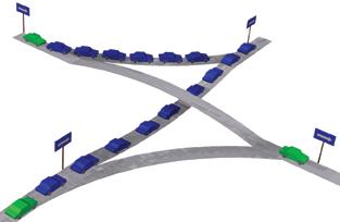
As discussed above, the first reaction to output contention is to buffer excess packets until they can exit the network. When the data structure implemented within such buffer memory is a single first-in-first-out (FIFO) queue (or an insufficient number of such queues), the risk arises for a phenomenon known as Head-of-Line (HOL) Blocking. This is illustrated in the figure on the right, using an analogy: packets in a network are like cars in a set of interconnecting highways. A FIFO queue is like one lane of a highway. If there is contention for one output of the network (the top right destination in the figure), and a queue fills up with packets destined to that output (the blue cars in the figure), packets destined to other outputs (the green cars in the figure) may be needlessly blocked from making forward progress: the packets at the head of the line block the packets behind them.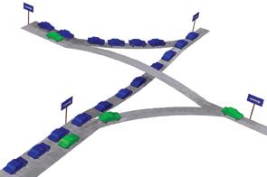
To remedy this situation, multi-lane highways are used, as ilustrated in the second figure on the right: a separate lane is allocated to each particular destination, thus "green" cars can freely proceed in their course without being blocked behind the waiting "blue" cars. Analogous phenomena appear in several popular network configurations; to resolve HOL blocking, multiple-queue data structures are needed within buffer memories. The straightforward solution calls for a separate queue for each and every network output, but this has an excessive cost in large networks. Compromise solutions are often used, with various complexity-performance tradeoffs; congestion management in such networks is still an open research topic.
0.2 Problems of Scale: Avoiding All-to-All Wiring
The second central problem in networking is to scale the interconnect to very large numbers n of end-stations, as mentioned at the beginning of this document. The all-to-all interconnection pattern that was illustrated in the top figure of section 0.1 can be implemented in two elementary fashions. For few and low-rate links, it can be implemented using time switching, i.e. by time-multiplexing all inputs into one, high-rate link, and then demultiplexing this link into all outputs. For higher rate links, time-multiplexing is not viable,
due to clock-frequency limitations;
the all-to-all pattern can still be implemented
using the interconnection topology shown on the right (top),
which is known as the crossbar
and is the most elementary space switching architecture.
For a number n of end-stations,
the crossbar has an O(n2) cost;
this is acceptable for small values of n,
but too expensive for large values.
In practice, when combined with buffering,
crossbars are used for switch sizes up to the range
n=32 to n=128;
beyond this, multi-stage architectures become less expensive.
For higher rate links, time-multiplexing is not viable,
due to clock-frequency limitations;
the all-to-all pattern can still be implemented
using the interconnection topology shown on the right (top),
which is known as the crossbar
and is the most elementary space switching architecture.
For a number n of end-stations,
the crossbar has an O(n2) cost;
this is acceptable for small values of n,
but too expensive for large values.
In practice, when combined with buffering,
crossbars are used for switch sizes up to the range
n=32 to n=128;
beyond this, multi-stage architectures become less expensive.
0.2.1 Multi-Stage Interconnection
For hundreds of ports or more, multi-stage architectures, or switching fabrics, can offer performance comparable to the crossbar but at lower cost. For even higher port counts, we are forced to limit performance to lower levels in order to achieve acceptable cost; a corresponding interconnect is illustrated in the bottom part of the figure, on the right --multi-stage networks are still the solution Multi-stage networks use more than one switches between a source and a destination station; in this way, network links are shared among multiple I/O ports, thus reducing the cost of the interconnection. The presence of multiple stages further complicates the issues of coordination among the multiple sources that were discussed above, because contention for resources may now occur further away (in terms of switch stages) from these sources: the network becomes an even more distributed system.0.2.2 Internal Blocking: Output Contention Variant
Multi-stage interconnection networks may suffer from internal blocking: specific flow patterns that would be feasible in an all-to-all interconnection architecture may not be feasible any more in the multi-stage network, due to intermediate, shared link limitations. In the example of the figure (bottom part), internal blocking appears for traffic patterns that are not sufficiently local, e.g. when two or more end-nodes that are connected to the same switch wish to communicate remotely i.e. not among themselves. Internal blocking is a variant of output contention: multiple sources "simultaneously" transmit information at an aggregate rate in excess of the capacity of one or more internal network links (or other resources); if we consider the sub-network up to the first "bottleneck" link, the phenomenon appears as output contention in that sub-network. Depending on the architecture of the multi-stage network, internal blocking may never appear ("non-blocking network"), or it may appear only in few, rare cases, or it may appear in many, frequent cases. The multi-stage interconnection at the beginning of section 0.1 (12x12 network, using 6x6 switches) presents rare internal blocking (e.g. when all 6 end-stations in the top and right half of the network want to communicate to the other 6 end-stations in the bottom and left half), while the less expensive interconnection in this section (bottom part of the figure) (12x12 network, using 4x4 switches) presents much more frequent internal blocking. Architecting networks for low internal blocking is one of our topics.
|
[Up: Table of Contents] [Slides 0. Introduction] |
[printer version, in PDF] [Next: 1.1 Throughput and Buffering] |
| Up to the Home Page of CS-534
|
© copyright
University of Crete, Greece.
Last updated: 11 March 2007, by M. Katevenis. |